American Samoa

American Samoa

ASPR Health Care Readiness State Highlights

ASPR Health Care Readiness by the Numbers


Hospital Preparedness Program (HPP)

HPP is a cooperative agreement administered by ASPR's National Healthcare Preparedness Programs (NHPP) Branch. It establishes the foundation for national health care readiness, promotes a consistent national focus to improve patient outcomes during emergencies, and enables rapid health care service resilience and recovery.

State Icon

1 Health Care Coalition (HCCs)

  • American Samoa Health Care Coalition
Handshake Icon

HCC Core Member Participation Rate

  • 100% of acute care hospitals
  • 100% of emergency medical services (EMS)
  • 100% of public health agencies
  • 100% of emergency management agencies
HPP Cooperative Agreement Funding COVID-19 Supplemental Funding Related Resources

For more details, see ASPR Health Care Readiness Programs Funding.

Total funding (all sources): $176,567

Alaska

Alaska

ASPR Health Care Readiness State Highlights
 

ASPR Health Care Readiness by the Numbers


Hospital Preparedness Program (HPP)

HPP is a cooperative agreement administered by ASPR's National Healthcare Preparedness Programs (NHPP) Branch. It establishes the foundation for national health care readiness, promotes a consistent national focus to improve patient outcomes during emergencies, and enables rapid health care service resilience and recovery.

State Icon

1 Health Care Coalition (HCC)

  • Alaska State Health Care Coalition

Handshake Icon

HCC Core Member Participation Rate

  • 100% of acute care hospitals

  • 100% of emergency medical services (EMS)

  • 100% of public health agencies

  • 100% of emergency management agencies

National Special Pathogen System (NSPS)

The NSPS is a nationwide systems-based network approach that builds on existing infrastructure and investments in preparing for infectious disease outbreaks. NSPS supports the urgent preparedness and response needs of hospitals, health systems, and health care providers related to treating patients with special pathogens.

Clipboard Icon

HPP Cooperative Agreement Recipient

Alaska Department of Health

Hospital Icon

Hospital Association Recipient

Alaska State Hospital & Nursing Home Association

Hospitals, health systems, and other health care entities receive COVID-19 Preparedness and Response Activities Cooperative Agreement funding via their hospital association.

HPP Cooperative Agreement FundingCOVID-19 Supplemental FundingRelated Resources

For more details, see ASPR Health Care Readiness Programs Funding.

  • Total funding (all sources): $1,719,748

  • Hospital Association: $856,737

  • HPP Cooperative Agreement Award: $863,011


Alabama

Alabama

ASPR Health Care Readiness State Highlights
 

ASPR Health Care Readiness by the Numbers


Hospital Preparedness Program (HPP)

HPP is a cooperative agreement administered by ASPR's National Healthcare Preparedness Programs (NHPP) Branch. It establishes the foundation for national health care readiness, promotes a consistent national focus to improve patient outcomes during emergencies, and enables rapid health care service resilience and recovery.

Ribbon Icon

Health Department Recipient

Alabama Department of
Public Health

State Icon

9 Health Care Coalitions (HCCs)

  • AL East Central District HCC

  • AL Jefferson County HCC

  • AL Mobile County Healthcare Emergency Response HCC

  • AL North Alabama HCC

  • AL Northeastern District HCC

  • AL Shoals HCC

  • AL Southeastern District HCC

  • AL Southwestern District HCC

  • AL West Central Alabama District HCC

Handshake Icon

HCC Core Member Participation Rate

  • 100% of acute care hospitals

  • 26% of emergency medical services (EMS)

  • 80% of public health agencies

  • 99% of emergency management agencies

National Special Pathogen System (NSPS)

The NSPS is a nationwide systems-based network approach that builds on existing infrastructure and investments in preparing for infectious disease outbreaks. NSPS supports the urgent preparedness and response needs of hospitals, health systems, and health care providers related to treating patients with special pathogens.

Clipboard Icon

HPP Cooperative Agreement Recipient

Alabama Department of Public Health

See above for more details, including HCC information.

Hospital Icon

Hospital Association Recipient

Alabama Hospital Association

Hospitals, health systems, and other health care entities receive COVID-19 Preparedness and Response Activities Cooperative Agreement funding via their hospital association. 
 

HPP Cooperative Agreement FundingCOVID-19 Supplemental FundingASPR Health Care Readiness: Stories from the Field
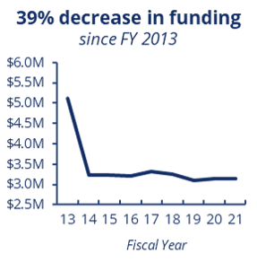
39 percent decrease in funding since FY 2013.

For more details, see ASPR Health Care Readiness Programs Funding.

  • Total funding (all sources): $4,495,753

  • Hospital Association: $2,495,882

  • HPP Cooperative Agreement Award: $1,999,871

ASPR Hospital Association COVID-19 Supplemental Funding Allows Rural Alabama Hospital to Continue Serving its Community 
 

View all Stories from the Field

Related Resources

SNS Training Video: Bariatric Bed Assembly - New Medline Model

SNS Training Video: Bariatric Bed Assembly - New Medline Model

Alternative Text for Time-Based Media

The following is a text alternative description for SNS Training Video: Bariatric Bed Assembly - New Medline Model.

[The video provides step by step demonstrations and instructional content on the assembly and testing of the new Medline Bariatric Bed.]

Unknown Male Narrator: Assembling the new Medline Bariatric Bed can be quite intimidating, but if you follow the steps provided in this video you will find that its much easier than you might think.

  1. The first thing you want to do is pull the mattress out of the tri-wall container. This will enable easy removal of the other parts.
  2. Lay out the two sections of the bed frame and align them so they are facing each other.
  3. Attach the two sections of the bedframe at the point where you see the mounting latches and rivets. Be sure they lock into place.
  4. Under the bed you will see a small bag containing tools needed to assemble the bed rail mounting brackets. Remove this bag and set it to the side.
  5. The bed comes with six bed rail mounting brackets. Two of them are short and four are long. Using the tools included in the kit attach the smaller mounting bracket first near the middle of the frame.
  6. Then, attach the longer mounting bracket to the ends of the frame before connecting to the smaller mounting bracket. Now, tighten the screws.
  7. Next, connect the head and foot motor connection cables.
  8. Now, you can connect the head/foot controller to the VGA connector.
  9. Then, plug in the A/C adapter.
  10. Now, you're ready to connect the head and foot sections of the bed ensuring that these lock into place before turning the bed over.
  11. Next, add the safety pin.
  12. At the foot of the bed make sure that the two parts of the gearbox output shaft are connected by pushing the two pieces together until the grooves lock into place.
  13. Now, it's time to add the drive shaft. Note: that the length can be adjusted by pushing the button near the center of the drive shaft and pushing the two sections together or pulling them apart.
  14. Now, push the drive shaft into the head end gearbox and the other end into the high-low motor output shaft. This is located under the frame of the head and foot sections.
  15. Connect the headboard and footboard sections to the bed frame, then slide the notches of the frame into the grooves on the headboard and footboard. Here is closer look at the gearbox and how it connects to the drive shaft. You can make further adjustments to the drive shaft if it's too long or too short.
  16. Carefully, turn the bed over.
  17. Now, you can add the brace assembly onto the bed frame. For each assembly, you will need - one bedrail mounting bracket, one adjustment clamp, three long bolts, three washers, three nuts, and two spacers.
  18. First, attach the bedrail mounting bracket to the bed frame using two bolts and two lug nuts.
  19. Next, secure the side adjustment clamp to the bedrail mounting bracket using two bolts, two spacers, and two lug nuts.
  20. Repeat these steps when adding the other cross brace assembly to the opposite side of the bed.
  21. Place each bedrail into the cross assembly by pulling the plunger pin and dropping the rail into place.
  22. The frame is now complete and you can now place the matter complete and you can now place the mattress onto the bed.
  23. Plug in the beds electrical cord to a power source.
  24. Before putting the bed into use, test it by using the control pad to operate through all phases of its operation. The six-function control pad is used for all bed operations.

If any problems arise during the test, recheck all electrical connections and mechanical hookups. In the even of a power outage, you can use the hand crank to manually raise or lower the beds head or foot sections independently. You can also raise or lower the entire bed.

[The video ends showing an assembled and fully functional Bariatric Bed.]

Montaje de Elevación Bariátrica

Montaje de Elevación Bariátrica

Descripción Alternativa para Medios-Basados en el Tiempo

La siguiente es una descripción alternativa de texto para el video de capacitación Montaje de Elevación Bariátrica.

[El video proporciona demostraciones paso a paso y contenido instructivo sobre el montaje del elevador bariátrico].

Narrador Masculino Desconocido: Un elevador de pacientes está diseñado para permitir que los cuidadores muevan de manera efectiva y fácil a una persona enferma. Este modelo puede levantar un máximo de 1200 libras y está diseñado principalmente para pacientes obesos. Al igual que la cama Bariatric, montar el elevador puede parecer un poco intimidante. Sin embargo, si sigue estos pasos le resultará bastante sencillo. Tenga en cuenta que para ensamblar esta unidad necesitará dos llaves inglesas ajustables grandes, estas no están incluidas en el juego.

  • Primero, retire las piezas del contenedor de tres paredes. Coloque las patas en la sección de la base. Estos se mantienen en su lugar mediante cuatro pasadores de enganche.
  • Ahora fije la viga de soporte central a la sección de la base con dos pernos.
  • A continuación, fije la riostra de la viga de soporte central a la viga de soporte central y la sección de la base.
  • Con un perno, coloque el brazo de extensión en la parte superior de la viga de soporte central. Este proceso tomará al menos dos personas. El brazo de extensión es pesado y debe mantenerse en su lugar mientras aprieta el perno.
  • Ahora, puede sujetar la parte inferior de la unidad de elevación hidráulica al soporte de la viga de soporte central. Esto también requiere al menos dos personas ya que la unidad de elevación hidráulica es pesada y debe mantenerse en su lugar mientras aprieta el perno.
  • Conecte la parte superior de la unidad de elevación hidráulica al soporte del brazo de extensión. Esto también requiere al menos dos personas ya que esta sección del elevador es muy pesada y también debe mantenerse en su lugar mientras aprieta el perno.
  • A continuación, coloque la base o la barra de trapecio en el gancho al final del brazo de extensión.
  • Coloque las seis cadenas de gancho en el extremo de la base o barra de trapecio. Los números que se muestran aquí se refieren a los eslabones de cada cadena.
  • A continuación, suelte la manija del gato de la viga de soporte central y fíjela a la unidad de elevación hidráulica. La manija del gato se bombea hacia arriba y hacia abajo para levantar al paciente. También se utiliza para ajustar la válvula de liberación hidráulica, que baja al paciente. Se incluye un cabestrillo para el paciente en el juego y debe colocarse debajo del paciente. Las seis cadenas de gancho del dispositivo de elevación están unidas a los seis puntos de elevación de la eslinga.

Nota: Para utilizar el dispositivo de elevación de pacientes, la cama bariátrica debe estar levantada; de lo contrario, las patas del dispositivo de elevación bariátrica no cabrán debajo de la cama.

El brazo de extensión de la pluma es ajustable. Cuando no está extendido, el dispositivo puede levantar un peso máximo de 1200 libras. Sin embargo, cuando se extiende la pluma, el peso máximo que puede levantar el dispositivo es de solo 800 libras.

[El video termina.]

SNS Training Video: Bariatric Lift Assembly

SNS Training Video: Bariatric Lift Assembly

Alternative Text for Time-Based Media

The following is a text alternative description for SNS Training Video: Bariatric Lift Assembly.

[The video provides step by step demonstrations and instructional content on the assembly of the Bariatric Lift.]

Unknown Male Narrator: A patient lift is designed to enable caretakers to effectively and easily move a sick person. This model can lift a maximum of 1200 pounds and is primarily designed for obese patients. Like the Bariatric bed, assembling the lift can appear a bit intimidating. However, if you follow these steps you will find it quite simple. Please note that in order to assemble this unit you will need two large adjustable crescent wrenches, these are not included in the set.

  • First, remove the parts from the tri-wall container. Attach the legs to the base section. These are held in place by four Hitch pins.
  • Now attach the center support beam to the base section with two bolts.
  • Next, attach the center support beam brace to center support beam and base section.
  • Using one bolt, attach the extension arm to the top of the center support beam. This process will take at least two people. The extension arm is heavy and must be held in place while tightening the bolt.
  • Now, you can attach the bottom of the hydraulic lift unit to the center support beam bracket. This also requires at least two people as the hydraulic lift unit is heavy and must be held in place while tightening the bolt.
  • Attach the top of the hydraulic lift unit to the extension arm bracket. This also requires at least two people as this section of the lift is very heavy and also must be held in place while tightening the bolt.
  • Next, attach the cradle or trapeze bar to the hook at the end of the extension arm.
  • Attach the six hook chains onto the end of the cradle or trapeze bar. The numbers shown here refer to the links in each chain.
  • Next, unclip the jack handle from the center support beam and attach it to the hydraulic lift unit. The jack handle is pumped up and down to raise the patient. It is also used to adjust the hydraulic release valve, which lowers the patient. A Patient Sling is included in the set and should be placed under the patient. The six hook chains of the lift device are attached to the sling's six lifting point.

Note: In order to use the patient lift device, the bariatric bed must be raised otherwise the legs of the bariatric lift device will not fit under the bed.

The boom extension arm is adjustable.When not extended, the device can lift a maximum weight of 1200 pounds. However, when the boom is extended the maximum weight the device can lift is just 800 pounds.

[The video ends.]

Montaje de cama bariátrica 2020 (Modelo Heredado)​

Montaje de cama bariátrica 2020 (Modelo Heredado)​

Descripción Alternativa para Medios-Basados en el Tiempo

La siguiente es una descripción alternativa de texto para el v ideo de capacitación Conjunto de cama bariátrica 2020 (Modelo Heredado) versión en español.

[El video proporciona demostraciones paso a paso y contenido instructivo sobre el ensamblaje y prueba de la cama bariátrica].

Narrador masculino desconocido: Montar una cama bariátrica puede parecer bastante intimidante, pero si sigue los pasos proporcionados en este video, encontrará que es mucho más fácil de lo que piensa. Tenga en cuenta que se requiere un pequeño juego de enchufes para sujetar los dos soportes de bloqueo ajustables a cada lado del marco de la cama. Estos no están incluidos en la caché de FMS.

  1. Lo primero que debe hacer es sacar el colchón del contenedor de tres paredes. Esto facilitará permitirá el acceso a las otras partes mas luego.

  2. Coloque las dos secciones del marco de la cama y alinee las para que queden paralelas enoyje las mitades del marco de la cama y conecte las con los pasadores adjuntos.

  3. Conecte el cable eléctrico al costado de las mitades del armazón de la cama.

  4. Abra las tapas de las aletas de las cajas de engranajes en al parte inferior del estribo y la cabecero esto facilitará el acceso más luego tenga en cuenta que la cabecera y el estribo son idénticos e intercambiables.

  5. Conecte las secciones de la cabecera y el pie de cama al marco de la cama luego deslice las muescas del marco en las ranuras de la cabecera y el pie de cama.

  6. Extienda la barra central haste que encaje en su lugar. Ahora, empuje la barra central en el conector de la caja de engranajes que se encuentra al pie de la cama debajo del marco cama debajo del marco. La barra debe estar por encima de las barras transversales que se encuentran debajo del marco de la cama. Que se muestra aquí es el conector con resorte de la caja de cambios al estribo. Aquí hay otro foto desde un ángulo diferente mirando hacia la barra central que se conecta a la caja de cambios. [Música]

  7. El marco ahora está completo y puede colocar el colchón en la cama.

  8. Ahora, coloque en los rieles laterales de la cama luego conecte los pasadores del riel lateral. Conecte el cable de alimentación de la cama a una fuente de alimentación antes de colocar la cama en uso. Pruébalo usando la almohadilla de control para operar en todas las fases de su funcionamiento. La almohadilla de control de 6 funciones se utiliza para todas las operaciones de la cama.

  9. Si surge algún problema durante la prueba, vuelva a verificar todas las conexiones eléctricas y mecánicas. En caso de un corte de energía, puede usar las manivelas para elevar o baje las secciones de la cabeza o los pies de la cama de forma independiente. También, puede subir o bajar toda la cama. Hay dos conectores separados uno ubicado en cada extremo de la cama. [Música]

[El video termina mostrando una cama bariátrica ensamblada y completamente funcional.]

SNS Training Video: Bariatric Bed Assembly 2020 (Legacy Model)

SNS Training Video: Bariatric Bed Assembly 2020 (Legacy Model)

Alternative Text for Time-Based Media

The following is a text alternative description for SNS Training Video: Bariatric Bed Assembly 2020 (Legacy Model) .

[The video provides step by step demonstrations and instructional content on the assembly and testing of the Bariatric Bed.]

Unknown Male Narrator: Assembling a Bariatric bed can appear to be quite intimidating, but if you follow the steps provided in this video you will find that its much easier than you might think. Please note that a small socket set is required in order to attach the two adjustable locking brackets to each side of the bed frame. These are not included in the FMS cache.

  1. The first thing you want to do is pull the mattress out of the tri-wall container. This will enable easy removal of the other parts.
  2. Lay out the two sections of the bed frame and align them so they ae parallel.
  3. Push the bed frame halves together and connect with the attached pins.
  4. Connect the electrical cable on the side of the bed frame halves.
  5. Open the flap covers of the gear boxes on the bottom of the footboard and headboard. This will make it easier to access later. Note: The headboard and footboard are identical and interchangeable.
  6. Connect the headboard and footboard sections to the bed frame then slide the notches on the frame into the grooves on the headboard and footboard.
  7. Extend the center rod until it locks into place.
  8. Now, push the center rod into the gear box connector which is located at the foot of the bed under the frame. the rod must be above the crossbars which are beneath the bed frame. Pictured here is the spring-loaded connector from the gear box to the footboard. Here is another photo from a different angle looking down at the center rod connecting to the gear box. The frame is now complete and you can place the mattress on the bed.
  9. Now, place the side rails on the bed.
  10. Next, connect the side rail pins.
  11. Plug in the bed's electrical cord to a power source.
  12. Before placing the bed into use, test it by using the control pad to operate it through all phases of its operation. The six function control pad is used for all bed operations.

If any problems arise during the test, recheck all electrical connections and mechanical hookups. In the event of a power outage, you can use the hand cranks to manually raise or lower the bed's head or foot sections independently. You can also raise or lower the entire bed. There are two separate connectors. One located at each end of the bed.

[The video ends showing an assembled and fully functional Bariatric Bed.]

Montaje de cama de​ uso general​ (GUB)

Montaje de cama de​ uso general​ (GUB)

Descripción Alternativa para Medios-Basados en el Tiempo

La siguiente es una descripción alternativa de texto para el video de capacitación SNS: Montaje de cama de uso general (GUB).

[Este video de capacitación comienza con una imagen de una cama de uso general (GUB) completamente ensamblada. El video proporciona una demostración visual e instrucciones para guiar al usuario a través del proceso de ensamblaje de una cama de uso general.]

Narrador masculino: Las camas GUB o de uso general se entregan en tres paredes con una etiqueta roja marcada como "Uso general". Estas camas no son muy difíciles de armar y pueden ser armadas por una sola persona. Para armar la cama:

  1. Primero desbloquee el clip ubicado cerca de la parte superior del marco y abra la cama.

  2. Acueste la cama boca abajo y levante las tres piernas para que apunten hacia arriba.

  3. Ahora asegure las cuatro bisagras ubicadas en cada extremo del marco de la cama. Para bloquear cada bisagra, simplemente empuje hacia abajo, preferiblemente con el pie, o si elige usar la mano, es una buena idea usar guantes para evitar rasguños, cortes u otras lesiones accidentales.

  4. Quite el colchón deslizándolo desde debajo del marco de la cama.

  5. Ahora voltee la cama y coloque el colchón sobre el armazón de la cama. Use los cuatro cierres de velcro ubicados en cada extremo del colchón para asegurarlo al marco de la cama.

El video termina mostrando la cama de uso general (GUB) completamente ensamblada].

Subscribe to